Laboratory
CITEEC’s Hydraulics Laboratory facilities allow to address problems related to almost any area of hydraulic engineering, including both pressurized and free-flowing flows. In recent years, the CITEEC Hydraulics Laboratory has specialized in the development of physical and numerical models related to urban water systems, for which it maintains close collaboration with the Sanitary and Environmental Engineering Laboratory.
In the scope of water supply, the laboratory has three circuits of pressure pipes to study the efficiency of this type of system. Among them, the physical model MEDUSA is a cutting-edge facility that models the urban water cycle in the city of A Coruña. The large number of measurement devices in the model is managed by advanced ICT systems that will allow the development of new management strategies based on the application of Artificial Intelligence and Machine Learning.
Regarding urban drainage, the laboratory has two large rainfall simulators, with areas of 36 and 100 m2 respectively, which simulate rainfall-runoff transformation processes in urban catchments. These models also consider water flows in drainage pipe networks and the interactions between the surface and its respective drainage system through gully pots and manholes. Works developed in these facilities address the modelling of hydraulic processes including flood studies, analysis of pollutant wash-off and transport, and the implementation of sustainable urban drainage systems (SUDS) for the improvement of urban water systems in terms of water quantity and quality
In addition to these permanent facilities, the laboratory also has space for projects related to natural aquatic systems such as rivers or reservoirs. Some examples of projects developed in this topic are:
- Development and calibration of surface water quality modell.
- Water quality monitoring stations in urban and natural water systems.
- Analysis through field studies and mathematical modelling of water quality disturbances by discharges of urban and industrial pollutant loads.
- River mouth processes (deltaic areas, estuaries).
- River hydraulics (margins and banks restoration).
- Hydraulic structures (dams and hydroelectric exploitations).
- Treatment plant hydraulics.
Infrastructure
The laboratory has an area of more than 1000 m2 with three independent water supply circuits that provide a maximum discharge of 60, 120 and 400 L/s. The floor is suitable for trucks and allows the construction of large physical models. Currently, the laboratory has a 30 m long channel, a 1:40 scale dam model, two physical models with rainfall simulators for urban hydrology studies, two systems of pressure pipes for the analysis of supply networks efficiency and a concept model of the urban water cycle in the city of A Coruña.
Rainfall-runoff simulator of a full-scale street section
This facility is a full-scale street section physical model of 36 m2 for studying rainfall-runoff processes and pollutants mobilization in urban catchments, including transport through gully pots and a drainage pipe system. Specific characteristics of the model are:
- Concrete pavement with a transverse and longitudinal slope of 2% and 0.5% respectively.
- Drippers based rainfall simulator that can generate rain intensities of 30, 50 and 80 mm/h.
- Upstream channel for generating surface run-off.
- Two gully pots and a downstream runoff channel to drain generated runoff into the pipe system.
- Drainage system made up of PVC pipes with diameters between 85 and 190 mm.
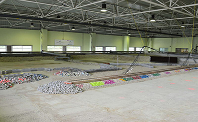
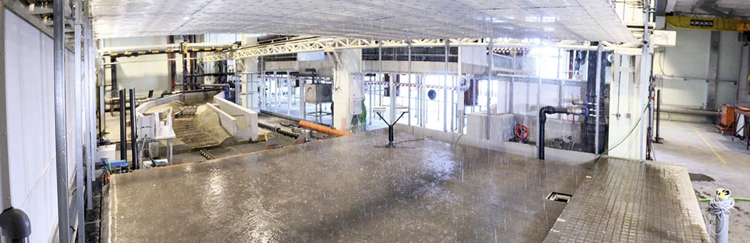
Scientific platform for urban runoff tests
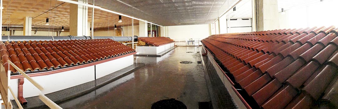
Full-scale physical model of an urban intersection for studying rainfall-runoff transformation processes and pollutants mobilization in urban catchments, considering roofs, an impervious concrete surface and a drainage pipe system. The characteristics of the model, which has a total surface area of 100 m2, are:
- One of the world largest rainfall simulators is installed, being able to generate constant rainfall intensities of 30, 50 or 80 mm/h.
- The surface of the model consists of the perpendicular intersection of two streets. The pavement is made of concrete with a transverse slope of 2% and a longitudinal slope of 1%. It has four interchangeable building modules for the analysis of different types of roofs and SUDS techniques, such as green roofs or filtering systems. As initial configuration, curved ceramic tile roofs with adjustable slope have been installed.
- The facility has four gully pots, four gutters and a transversal grid installed downstream that drain the generated runoff into four manholes. Six sections of transparent plastic pipes with a diameter of 200 mm complete the model’s drainage system.
- It is possible to generate surface runoff and pipe flow inputs at the upstream of both streets that make up the physical model.
Integral model of the urban water cycle of A Coruña – Medusa
This facility represents the functioning of integrated urban water management in the city of A Coruña. First, this conceptual model has a catchment area where surface runoff can be generated, a reservoir and a DWTP at the headwaters. Then, the water is distributed through a network of pipes monitoring the water use of the different sectors in the city by a large number of sensors. Finally, the facility has a WWTP downstream of the model from which the water is recirculated. In addition to its informative nature, the large number of measurement devices is managed by advanced ICT systems, which will allow the development of new management strategies based on the application of Artificial Intelligence and Machine Learning.
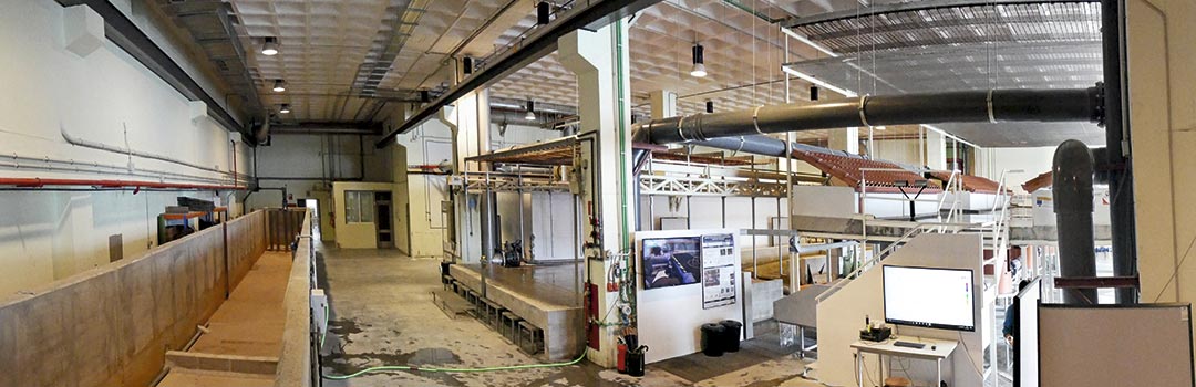
Bens WWTP flume facility
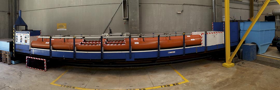
Test bench that uses real urban wastewater for the analysis of the performance of different types of pipes against physical and biological in-sewer processes, such as accumulation, erosion and transport of sediments. This facility is placed in the pre-treatment building of the WWTP of A Coruña in order to have a continuous and representative supply of wastewater, and has the support and instrumentation of the Hydraulics and Sanitary and Environmental Engineering Laboratories of CITEEC. The main characteristics are:
- The facility consists of two tanks located at the ends of a metal bench 10 m long and 0.8 m wide, which serves as support for the pipes to be tested and whose slope is adjustable between -0.5 and 6%.
- The urban wastewater is introduced in the inlet tank from the pre-treatment system of the WWTP. Water discharge is regulated in this tank and conducted to each pipe by means of a gate valve and v-notch weirs. Finally, the wastewater passes through the pipes towards an outlet tank with an automatic gate where the boundary conditions can be set for the different experiments.
- During the experiments, flow rates, depths and velocities in the tested pipes and pollutant loads in both tanks can be continuously measured by means of turbidity and light absorbance probes. In addition, automatic samplers are available for the collection of water samples in both tanks.
- Finally, a photogrammetric technique (Structure from Motion) has been optimized to obtain deposited sediment volumes and analyze bed forms.
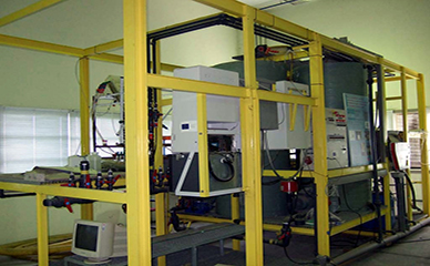
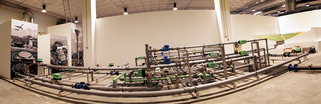
Pipe system panel
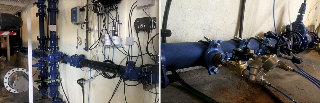
This facility consists of a circuit of pressurized pipes for analyzing processes that influence the generation of deposits in drinking water distribution pipes, which are susceptible to increase occasionally water turbidity. This facility is directly connected to A Coruña’s municipal water supply, so it is possible to continuously monitor water characteristics of the system from the laboratory. Specific characteristics are:
- Pipes with 100 mm of diameter and valves for establishing different flow configurations.
- A Panametrics AT600 ultrasonic flowmeter and a UNIK5000 pressure sensor are available for online recording of hydraulic variables.
- The panel has additionally two water sampling points, a particle counter CRIUS CounterSense, and a compact S::CAN system for online physical-chemical characterization by measuring quality parameters such as pH, temperature, conductivity, oxygen content, nitrates, nitrites, turbidity, residual chlorine or color.
Pressure pipe system
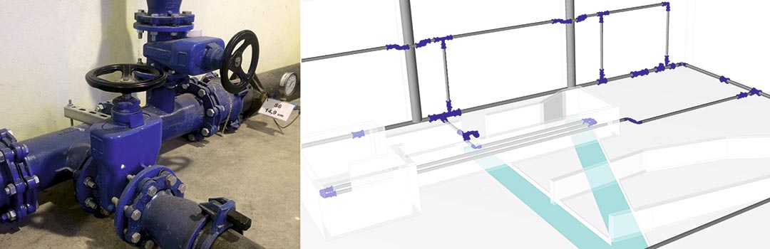
Network of pressure pipes for studying head losses in water supply systems. The facility is also used for teaching practices where pressure pipe flows and typical head losses are explained in a very visual and practical way.
Horizontal channel
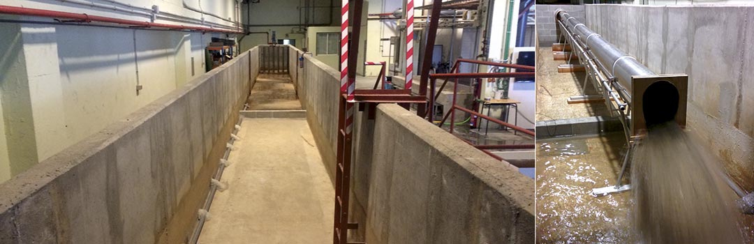
The channel is 30 m long and has a 2 m wide and 1.5 m depth cross-section. Its range of application includes studies of interposed channel structures, sediment transport analysis, and serving as enclosure for steep slope channels such as fish ladders. In addition, the characteristics of the channel make it optimal for experimental work in aerial or buried pipelines, including hydraulic flow characterization, cross-section optimization, improvement of pipe rehabilitation techniques, or infiltration and exfiltration studies.
Ocaña 2 Dam
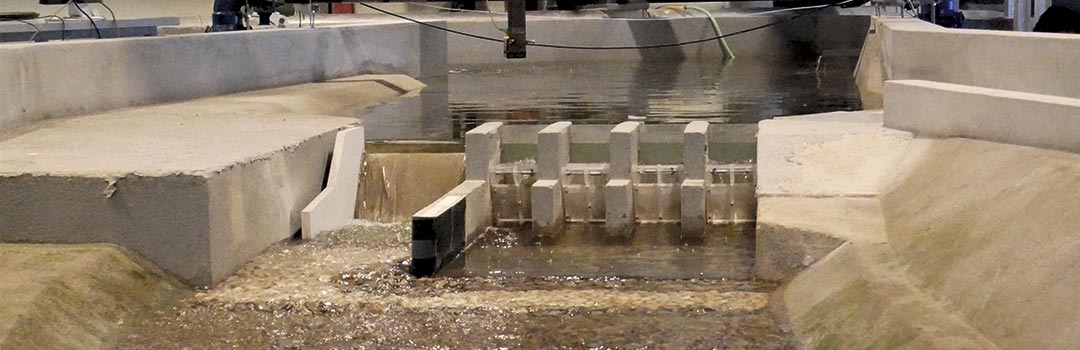 Physical model (1:40 scale) of a dam projected for the hydroelectric exploitation Ocaña 2 (Ecuador). The objective of this facility is to be used as the basis for the optimization of the spillway gates and erosion protections. In addition, the facility is currently used for teaching practices.
Instrumentation
The laboratory has a wide range of instrumentation to measure and monitor hydraulic and water quality variables for both pressurized and open channel flows. This equipment, together with high-precision data acquisition systems, is available for laboratory users to carry out a wide variety of experimental works. The main equipment available at the Hydraulics Laboratory is:
Velocity meters
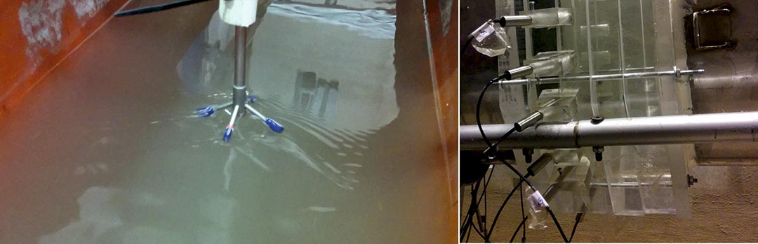
These equipments estimate the speed of a fluid from the changes of position of its particles between two consecutive acoustic pulses. CITEEC’s Hydraulics Laboratory has seven 3D doppler equipment (Sontek, Nortek) for obtaining high-resolution 3D punctual velocities. In addition, there are two DOP2000 (Signal Processing) devices that use the same principle to obtain 1D velocity profiles. Finally, a UB-Lab (Ubertone) velocity profiler has been acquired. This device also measure acoustic turbidity to estimate water quality parameters.
Particle Image Velocimetry (PIV)
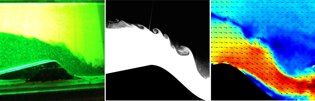
A Particle Image Velocimetry (PIV) and Laser Induced Fluorescence (LIF) device (LaVision) is available for laboratory users. This equipment generates pulses of a laser plane illuminating the particles suspended in a fluid, which are artificially seeded if they are not naturally present. Several cameras synchronized with the laser pulses capture images, which are analyzed using statistical correlation techniques to estimate the movement of the particles between two consecutive images. This technique obtains precise velocity fields within the generated laser plane as result. It is also possible to determine solute concentrations by using the LIF technique to analyse for example flows of different densities.
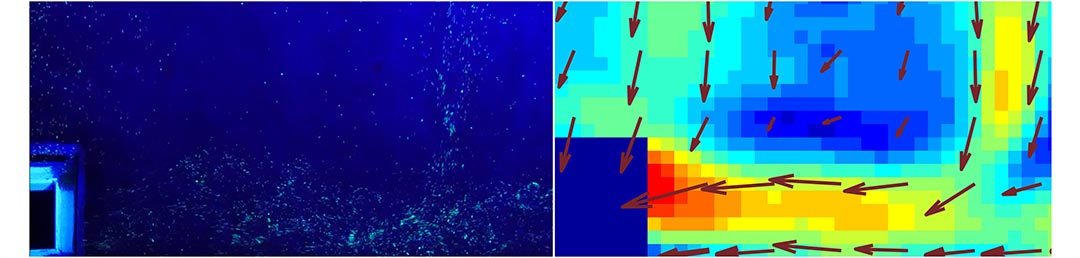
In addition, a low-cost LSPIV (Large Scale Particle Image Velocimetry) methodology has been developed and optimized for the characterization of the shallow overland flows generated on the laboratory’s rainfall simulators. This method uses fluorescent particles and UVA illumination to avoid the interference of raindrops in the flow images, which are taken by conventional cameras and subsequently used to determine the velocity of the particles present in the flow.
Disdrometer
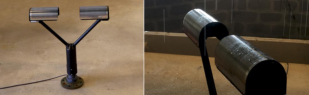
Parsivel2 disdrometer (OTT) provides detailed information on different variables that characterize a rain event, such as intensity or raindrop size and velocity distributions. This data is highly relevant in pollutant wash-off and soil erosion studies, where rain energy is key in the detachment of surface particles. This device has been used to calibrate the laboratory’s rainfall simulators, achieving raindrop size distributions very similar to those measured in real local rainfall. It is available to accurate characterize rain events or study the influence of rain energy on sediment wash-off and soil erosion experiments.
Depth sensors
20 ultrasonic distance sensors (Pepperl+Fuchs) are available to determine water depths and levels in model surfaces, channels, non-pressurized pipes, weirs and deposits.
Flow meters
First, there are six electromagnetic flow meters permanently installed in the laboratory’s water supply circuits. Another six Panametrics ultrasonic flowmeters measure the pressurized water flows that supply the laboratory’s physical models, and can be repositioned according to the needs of each project. In addition, two ISCO area-velocity flowmeters have been acquired to measure open channel flows. Finally, classic hydrometric equipment such as electromagnetic current meters (OTT) are also available.
Water quality measurement
Four probes for the measurement of total suspended solids (TSS) and another four probes for recording conductivity are available in the laboratory. These devices (S::CAN) allow the continuous measurement of pollutant mobilization (both their solid and dissolved fractions) in the laboratory’s urban drainage models.
Pressure sensors
Pressure sensors (Druck/ ) are used for online and precise recording of pressures in pressurized pipe circuits. These devices are also used submerged to estimate levels in deposit and depths in open channel flows.